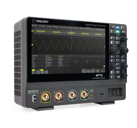
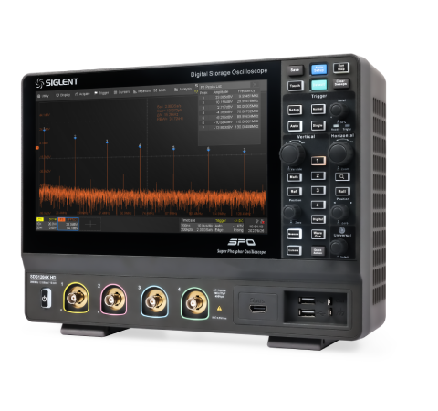
SDS1000X HD Digital Storage Oscilloscope
Siglent Technologies Co.
Main Features
- 100 MHz, 200 MHz bandwidth models
- 12-bit high resolution
- Sampling rate up to 2 GSa/s
- Memory depth up to 100 Mpts
- Waveform capture rate up to 500,000 wfm/s (Sequence mode)
- Noise floor as low as 70 μVrms at 200 MHz full bandwidth
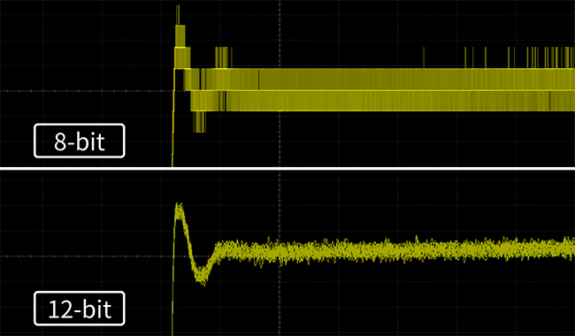
12-bit high resolution: perfectly restore waveform details
SDS1000X HD adopts a 12-bit analog-to-digital converter, which can achieve 4096 quantization levels, which is 16 times the signal resolution of traditional 8-bit oscilloscopes. Combined with the excellent noise floor, it can make the captured waveforms appear more clearly on the screen, which is conducive to the user's observation as well as accurate measurement.
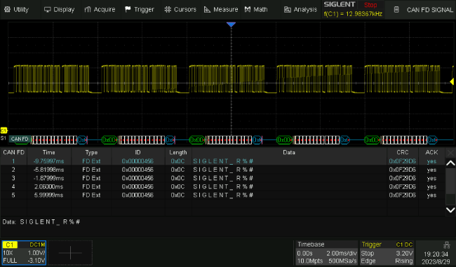
Standard 7 kinds of decoding: suitable for multiple scenarios
SDS1000X HD comes standard with I2C, SPI, UART, CAN, LIN, CAN FD, FlexRay, and the decoding results can be displayed in hexadecimal, decimal, binary, or ASCII format, and two parallel buses can be decoded at the same time, each of which is displayed as a graphic icon on the left side of the screen. In addition, the settings for the signals and the bus configurations can be synchronized to the triggers through the "Copy to trigger" function.
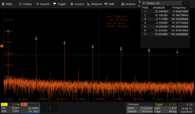
FFT: perfect combination of time and frequency domain
With hardware accelerated FFT function, the maximum number of operation points is 2Mpts, which provides superior spectral resolution while still maintaining a high spectral refresh rate. FFT supports multiple window functions, three modes of normal, average and maximum hold, and can automatically mark the peak points and form a list.
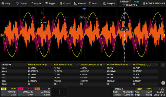
Power Analysis: beneficial to power supply design
Power Analysis can help users to quickly measure and analyze a variety of items in the power electronics field, such as power quality, harmonics, inrush current, switching loss, etc. Power Analysis can also be used to analyze the power loop response in combination with Bode Plot. When you turn on the power analysis function, you can use the voltage and current probes correctly according to the “Connection Guide”.
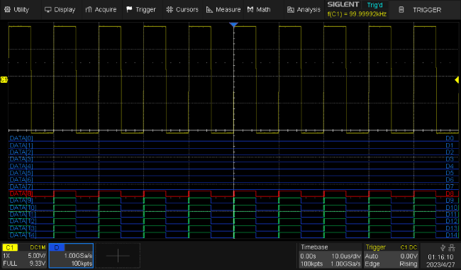
16 digital channels: realizing mixed signal acquisition and analysis
16 Channels Logic Analyzer can add 16 digital channels to the instrument without affecting other test functions, which can quickly solve the problems of analog-digital mixed-signal design and analysis.
Specification
| Bandwidth | 100 MHz 、200 MHz |
| Vertical resolution | 12-bit |
| Sample rate (Max.) |
One channel mode: 2 GSa/s, Two channel mode: 1 GSa/s, Four channel mode: 500 MSa/s |
| Analog channels | 2/4 + EXT |
| Memory depth (Max.) |
One channel mode: 100 Mpts/ch, Two channel mode: 50 Mpts/ch, Four channel mode: 25 Mpts/ch |
| Waveform capture rate (Max.) |
Normal mode : 120,000 wfm/s; Sequence mode : 500,000 wfm/s |
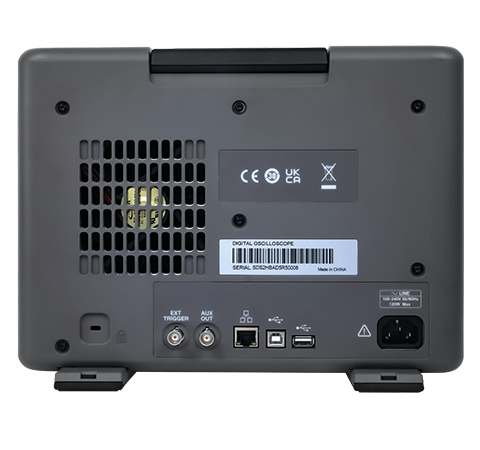
| I/O | USB 2.0 Host x3, USB 2.0 Device, 10 M / 100 M LAN, External trigger, Auxiliary output (TRIG OUT, PASS/FAIL), SBUS (Siglent MSO) |
| Serial trigger and decode (Standard) | I2C, SPI, UART, CAN, LIN, CAN FD(Decode Only), FlexRay(Decode Only) |
| Trigger type | Edge, Slope, Pulse width, Window, Runt, Interval, Dropout, Pattern, Video, Qualified, Nth edge, Delay, Setup/Hold time, Serial |
| Digital channel | 16-channel; maximum sample rate up to 1 GSa/s; record length up to 10 Mpts |
| Math | 4 traces 2 Mpts FFT, Filter, +, -, x, ÷, ∫dt, d/dt, √, Identity, Negation, Absolute, Sign, ex, 10x, ln, lg, Interpolation, MaxHold, MinHold, ERES, Average. Supports formula editor |
| Data analysis | Search, Navigate, History, Mask Test, Counter, Bode plot, and Power Analysis |
| USB AWG module (option) | One channel, 25 MHz, sample rate of 125 MHz, wave length of 16 kpts, isolated output |
| Display | 10.1 TFT-LCD with capacitive touch screen (1024*600) |

